
Annotation of text copyright ©2007 David Trumbull, Agathon Associates. All Rights Reserved.
Here begins Vitruvius' Book X on architecture, being the
continuation from Book IX.
Introduction
1. In the famous and important Greek city of Ephesus there is said to be an
ancient ancestral law, the terms of which are severe, but its justice is not
inequitable. When an architect accepts the charge of a public work, he has to
promise what the cost of it will be. His estimate is handed to the magistrate,
and his property is pledged as security until the work is done. When it is
finished, if the outlay agrees with his statement, he is complimented by decrees
and marks of honour. If no more than a fourth has to be added to his estimate,
it is furnished by the treasury and no penalty is inflicted. But when more than
one fourth has to be spent in addition on the work, the money required to finish
it is taken from his property. 2. Would to God that this were also a law of the Roman people, not merely for
public, but also for private buildings. For the ignorant would no longer run
riot with impunity, but men who are well qualified by an exact scientific
training would unquestionably adopt the profession of architecture. Gentlemen
would not be misled into limitless and prodigal expenditure, even to ejectments
from their estates, and the architects themselves could be forced, by fear of
the penalty, to be more careful in calculating and stating the limit of expense,
so that gentlemen would procure their buildings for that which they had
expected, or by adding only a little more. It is true that men who can afford to
devote four hundred thousand to a work may hold on, if they have to add another
hundred thousand, from the pleasure which the hope of finishing it gives them;
but if they are loaded with a fifty per cent increase, or with an even greater
expense, they lose hope, sacrifice what they have already spent, and are
compelled to leave off, broken in fortune and in spirit.
3. This fault appears not only in the matter of buildings, but also in the
shows given by magistrates, whether of gladiators in the forum or of plays on
the stage. Here neither delay nor postponement is permissible, but the
necessities of the case require that everything should be ready at a fixed
time,—the seats for the audience, the awning drawn over them, and whatever, in
accordance with the customs of the stage, is provided by machinery to please the
eye of the people. These matters require careful thought and planning by a well
trained intellect; for none of them can be accomplished without machinery, and
without hard study skilfully applied in various ways. 4. Therefore, since such are our traditions and established practices, it is
obviously fitting that the plans should be worked out carefully, and with the
greatest attention, before the structures are begun. Consequently, as we have no
law or customary practice to compel this, and as every year both praetors and
aediles have to provide machinery for the festivals, I have thought it not out
of place, Emperor, since I have treated of buildings in the earlier books, to
set forth and teach in this, which forms the final conclusion of my treatise,
the principles which govern machines. Chapter One
Machines and Implements
1. A machine is a combination of timbers fastened together, chiefly
efficacious in moving great weights. Such a machine is set in motion on
scientific principles in circular rounds, which the Greeks call κυλικη κἱνησις.
There is, however, a class intended for climbing, termed in Greek ἁκροβατικὁν,
another worked by air, which with them is called πνευματικὁν, and a third for
hoisting; this the Greeks named βαρουλκὁς. In the climbing class are machines so
disposed that one can safely climb up high, by means of timbers set up on end
and connected by crossbeams, in order to view operations. In the pneumatic
class, air is forced by pressure to produce sounds and tones as in an
ὁργανον. 2. In the hoisting class, heavy weights are removed by machines which raise
them up and set them in position. The climbing machine displays no scientific
principle, but merely a spirit of daring. It is held together by dowels and
crossbeams and twisted lashings and supporting props. A machine that gets its
motive power by pneumatic pressure will produce pretty effects by scientific
refinements. But the hoisting machine has opportunities for usefulness which are
greater and full of grandeur, and it is of the highest efficacy when used with
intelligence. 3. Some of these act on the principle of the μηχανἡ, others on that of the
ὁργανον. The difference between "machines" and "engines" is obviously this, that
machines need more workmen and greater power to make them take effect, as for
instance ballistae and the beams of presses. Engines, on the other hand,
accomplish their purpose at the intelligent touch of a single workman, as the
scorpio or anisocycli when they are turned. Therefore engines, as well as
machines, are, in principle, practical necessities, without which nothing can be
unattended with difficulties. 4. All machinery is derived from nature, and is founded on the teaching and
instruction of the revolution of the firmament. Let us but consider the
connected revolutions of the sun, the moon, and the five planets, without the
revolution of which, due to mechanism, we should not have had the alternation of
day and night, nor the ripening of fruits. Thus, when our ancestors had seen
that this was so, they took their models from nature, and by imitating them were
led on by divine facts, until they perfected the contrivances which are so
serviceable in our life. Some things, with a view to greater convenience, they
worked out by means of machines and their revolutions, others by means of
engines, and so, whatever they found to be useful for investigations, for the
arts, and for established practices, they took care to improve step by step on
scientific principles. 5. Let us take first a necessary invention, such as clothing, and see how the
combination of warp and woof on the loom, which does its work on the principle
of an engine, not only protects the body by covering it, but also gives it
honourable apparel. We should not have had food in abundance unless yokes and
ploughs for oxen, and for all draught animals, had been invented. If there had
been no provision of windlasses, pressbeams, and levers for presses, we could
not have had the shining oil, nor the fruit of the vine to give us pleasure, and
these things could not be transported on land without the invention of the
mechanism of carts or waggons, nor on the sea without that of ships. 6. The discovery of the method of testing weights by steelyards and balances
saves us from fraud, by introducing honest practices into life. There are also
innumerable ways of employing machinery about which it seems unnecessary to
speak, since they are at hand every day; such as mills, blacksmiths' bellows,
carriages, gigs, turning lathes, and other things which are habitually used as
general conveniences. Hence, we shall begin by explaining those that rarely come
to hand, so that they may be understood. Chapter Two
Hoisting Machines
1. First we shall treat of those machines which are of necessity made ready
when temples and public buildings are to be constructed. Two timbers are
provided, strong enough for the weight of the load. They are fastened together
at the upper end by a bolt, then spread apart at the bottom, and so set up,
being kept upright by ropes attached at the upper ends and fixed at intervals
all round. At the top is fastened a block, which some call a "rechamus." In the
block two sheaves are enclosed, turning on axles. The traction rope is carried
over the sheave at the top, then let fall and passed round a sheave in a block
below. Then it is brought back to a sheave at the bottom of the upper block, and
so it goes down to the lower block, where it is fastened through a hole in that
block. The other end of the rope is brought back and down between the legs of
the machine. 2. Socket-pieces are nailed to the hinder faces of the squared timbers at the
point where they are spread apart, and the ends of the windlass are inserted
into them so that the axles may turn freely. Close to each end of the windlass
are two holes, so adjusted that handspikes can be fitted into them. To the
bottom of the lower block are fastened shears made of iron, whose prongs are
brought to bear upon the stones, which have holes bored in them. When one end of
the rope is fastened to the windlass, and the latter is turned round by working
the handspikes, the rope winds round the windlass, gets taut, and thus it raises
the load to the proper height and to its place in the work. 3. This kind of machinery, revolving with three sheaves, is called a
trispast. When there are two sheaves turning in the block beneath and three in
the upper, the machine is termed a pentaspast. But if we have to furnish
machines for heavier loads, we must use timbers of greater length and thickness,
providing them with correspondingly large bolts at the top, and windlasses turning at the
bottom. When these are ready, let forestays be attached and left lying slack in
front; let the backstays be carried over the shoulders of the machine to some
distance, and, if there is nothing to which they can be fastened, sloping piles
should be driven, the ground rammed down all round to fix them firmly, and the
ropes made fast to them. 4. A block should then be attached by a stout cord to the top of the machine,
and from that point a rope should be carried to a pile, and to a block tied to
the pile. Let the rope be put in round the sheave of this block, and brought
back to the block that is fastened at the top of the machine. Round its sheave
the rope should be passed, and then should go down from the top, and back to the
windlass, which is at the bottom of the machine, and there be fastened. The
windlass is now to be turned by means of the handspikes, and it will raise the
machine of itself without danger. Thus, a machine of the larger kind will be set
in position, with its ropes in their places about it, and its stays attached to
the piles. Its blocks and traction ropes are arranged as described above. 5. But if the loads of material for the work are still more colossal in size
and weight, we shall not entrust them to a windlass, but set in an axle-tree,
held by sockets as the windlass was, and carrying on its centre a large drum,
which some term a wheel, but the Greeks call it ἁμφἱεσις or περιθἡκιον. 6. And the blocks in such machines are not arranged in the same, but in a
different manner; for the rows of sheaves in them are doubled, both at the
bottom and at the top. The traction rope is passed through a hole in the lower
block, in such a way that the two ends of the rope are of equal length when it
is stretched out, and both portions are held there at the lower block by a cord
which is passed round them and lashed so that they cannot come out either to the
right or the left. Then the ends of the rope are brought up into the block at
the top from the outside, and passed down over its lower sheaves, and so return
to the bottom, and are passed from the inside to the sheaves in the lowest
block, and then
are brought up on the right and left, and return to the top and round the
highest set of sheaves. 7. Passing over these from the outside, they are then carried to the right
and left of the drum on the axle-tree, and are tied there so as to stay fast.
Then another rope is wound round the drum and carried to a capstan, and when
that is turned, it turns the drum and the axle-tree, the ropes get taut as they
wind round regularly, and thus they raise the loads smoothly and with no danger.
But if a larger drum is placed either in the middle or at one side, without any
capstan, men can tread in it and accomplish the work more expeditiously. 8. There is also another kind of machine, ingenious enough and easy to use
with speed, but only experts can work with it. It consists of a single timber,
which is set up and held in place by stays on four sides. Two cheeks are nailed
on below the stays, a block is fastened by ropes above the cheeks, and a
straight piece of wood about two feet long, six digits wide, and four digits
thick, is put under the block. The blocks used have each three rows of sheaves
side by side. Hence three traction ropes are fastened at the top of the machine.
Then they are brought to the block at the bottom, and passed from the inside
round the sheaves that are nearest the top of it. Then they are brought back to
the upper block, and passed inwards from outside round the sheaves nearest the
bottom. 9. On coming down to the block at the bottom, they are carried round its
second row of sheaves from the inside to the outside, and brought back to the
second row at the top, passing round it and returning to the bottom; then from
the bottom they are carried to the summit, where they pass round the highest row
of sheaves, and then return to the bottom of the machine. At the foot of the
machine a third block is attached. The Greeks call it ἑπἁγων, but our people
"artemon." This block fastened at the foot of the machine has three sheaves in
it, round which the ropes are passed and then delivered to men to pull. Thus,
three rows of men, pulling without a capstan, can quickly raise the load to the
top. 10. This kind of machine is called a polyspast, because of the many revolving
sheaves to which its dexterity and despatch are due. There is also this
advantage in the erection of only a single timber, that by previously inclining
it to the right or left as much as one wishes, the load can be set down at one
side. All these kinds of machinery described above are, in their principles, suited
not only to the purposes mentioned, but also to the loading and unloading of
ships, some kinds being set upright, and others placed horizontally on revolving
platforms. On the same principle, ships can be hauled ashore by means of
arrangements of ropes and blocks used on the ground, without setting up
timbers. 11. It may also not be out of place to explain the ingenious procedure of
Chersiphron. Desiring to convey the shafts for the temple of Diana at Ephesus
from the stone quarries, and not trusting to carts, lest their wheels should be
engulfed on account of the great weights of the load and the softness of the
roads in the plain, he tried the following plan. Using four-inch timbers, he
joined two of them, each as long as the shaft, with two crosspieces set between
them, dovetailing all together, and then leaded iron gudgeons shaped like
dovetails into the ends of the shafts, as dowels are leaded, and in the woodwork
he fixed rings to contain the pivots, and fastened wooden cheeks to the ends.
The pivots, being enclosed in the rings, turned freely. So, when yokes of oxen
began to draw the four-inch frame, they made the shaft revolve constantly,
turning it by means of the pivots and rings. 12. When they had thus transported all the shafts, and it became necessary to
transport the architraves, Chersiphron's son Metagenes extended the same
principle from the transportation of the shafts to the bringing down of the
architraves. He made wheels, each about twelve feet in diameter, and enclosed
the ends of the architraves in the wheels. In the ends he fixed pivots and rings
in the same way. So when the four-inch frames were drawn by oxen, the wheels
turned on the pivots enclosed in the rings, and the architraves, which were
enclosed like axles in
the wheels, soon reached the building, in the
same way as the shafts. The rollers used for smoothing the walks in palaestrae
will serve as an example of this method. But it could not have been employed
unless the distance had been short; for it is not more than eight miles from the
stone-quarries to the temple, and there is no hill, but an uninterrupted
plain. 13. In our own times, however, when the pedestal of the colossal Apollo in
his temple had cracked with age, they were afraid that the statue would fall and
be broken, and so they contracted for the cutting of a pedestal from the same
quarries. The contract was taken by one Paconius. This pedestal was twelve feet
long, eight feet wide, and six feet high. Paconius, with confident pride, did
not transport it by the method of Metagenes, but determined to make a machine of
a different sort, though on the same principle. 14. He made wheels of about fifteen feet in diameter, and in these wheels he
enclosed the ends of the stone; then he fastened two-inch crossbars from wheel
to wheel round the stone, encompassing it, so that there was an interval of not
more than one foot between bar and bar. Then he coiled a rope round the bars,
yoked up his oxen, and began to draw on the rope. Consequently as it uncoiled,
it did indeed cause the wheels to turn, but it could not draw them in a line
straight along the road, but kept swerving out to one side. Hence it was
necessary to draw the machine back again. Thus, by this drawing to and fro,
Paconius got into such financial embarrassment that he became insolvent. 15. I will digress a bit and explain how these stone-quarries were
discovered. Pixodorus was a shepherd who lived in that vicinity. When the people
of Ephesus were planning to build the temple of Diana in marble, and debating
whether to get the marble from Paros, Proconnesus, Heraclea, or Thasos,
Pixodorus drove out his sheep and was feeding his flock in that very spot. Then
two rams ran at each other, and, each passing the other, one of them, after his
charge, struck his horns against a
rock, from which a fragment of extremely white
colour was dislodged. So it is said that Pixodorus left his sheep in the
mountains and ran down to Ephesus carrying the fragment, since that very thing
was the question of the moment. Therefore they immediately decreed honours to
him and changed his name, so that instead of Pixodorus he should be called
Evangelus. And to this day the chief magistrate goes out to that very spot every
month and offers sacrifice to him, and if he does not, he is punished. Chapter Three
The Elements of Motion
1. I have briefly set forth what I thought necessary about the principles of
hoisting machines. In them two different things, unlike each other, work
together, as elements of their motion and power, to produce these effects. One
of them is the right line, which the Greeks term εὑθεια; the other is the
circle, which the Greeks call κυκλωτἡ; but in point of fact, neither rectilinear
without circular motion, nor revolutions, without rectilinear motion, can
accomplish the raising of loads. I will explain this, so that it may be
understood. 2. As centres, axles are inserted into the sheaves, and these are fastened in
the blocks; a rope carried over the sheaves, drawn straight down, and fastened
to a windlass, causes the load to move upward from its place as the handspikes
are turned. The pivots of this windlass, lying as centres in right lines in its
socket-pieces, and the handspikes inserted in its holes, make the load rise when
the ends of the windlass revolve in a circle like a lathe. Just so, when an iron
lever is applied to a weight which a great many hands cannot move, with the
fulcrum, which the Greeks call ὑπομὁχλιον, lying as a centre in a right line
under the lever, and with the tongue of the lever placed under the weight, one
man's strength, bearing down upon the head of it, heaves up the weight. 3. For, as the shorter fore part of the lever goes under the weight from the
fulcrum that forms the centre, the head of it, which is farther away from that
centre, on being depressed, is made to describe a circular movement, and thus by
pressure brings to an equilibrium the weight of a very great load by means of a
few hands. Again, if the tongue of an iron lever is placed under a weight, and
its head is not pushed down, but, on the contrary, is heaved up, the tongue,
supported on the surface of the ground, will treat that as the weight, and the
edge of the weight itself as the fulcrum. Thus, not so easily as by pushing
down, but by motion in the opposite direction, the weight of the load will
nevertheless be raised. If, therefore, the tongue of a lever lying on a fulcrum
goes too far under the weight, and its head exerts its pressure too near the
centre, it will not be able to elevate the weight, nor can it do so unless, as
described above, the length of the lever is brought to equilibrium by the
depression of its head. 4. This may be seen from the balances that we call steelyards. When the
handle is set as a centre close to the end from which the scale hangs, and the
counterpoise is moved along towards the other arm of the beam, shifting from
point to point as it goes farther or even reaches the extremity, a small and
inferior weight becomes equal to a very heavy object that is being weighed, on
account of the equilibrium that is due to the levelling of the beam. Thus, as it
withdraws from the centre, a small and comparatively light counterpoise, slowly
turning the scale, makes a greater amount of weight rise gently upwards from
below. 5. So, too, the pilot of the biggest merchantman, grasping the steering oar
by its handle, which the Greeks call οἱαξ, and with one hand bringing it to the
turning point, according to the rules of his art, by pressure about a centre,
can turn the ship, although she may be laden with a very large or even enormous
burden of merchandise and provisions. And when her sails are set only halfway up
the mast, a ship cannot run quickly; but when the yard is hoisted to the top,
she makes much quicker progress, because then the sails get the wind, not when
they are[292] too
close to the heel of the mast, which represents the centre, but when they have
moved farther away from it to the top. 6. As a lever thrust under a weight is harder to manage, and does not put
forth its strength, if the pressure is exerted at the centre, but easily raises
the weight when the extreme end of it is pushed down, so sails that are only
halfway up have less effect, but when they get farther away from the centre, and
are hoisted to the very top of the mast, the pressure at the top forces the ship
to make greater progress, though the wind is no stronger but just the same.
Again, take the case of oars, which are fastened to the tholes by loops,—when
they are pushed forward and drawn back by the hand, if the ends of the blades
are at some distance from the centre, the oars foam with the waves of the sea
and drive the ship forward in a straight line with a mighty impulse, while her
prow cuts through the rare water. 7. And when the heaviest burdens are carried on poles by four or six porters
at a time, they find the centres of balance at the very middle of the poles, so
that, by distributing the dead weight of the burden according to a definitely
proportioned division, each labourer may have an equal share to carry on his
neck. For the poles, from which the straps for the burden of the four porters
hang, are marked off at their centres by nails, to prevent the straps from
slipping to one side. If they shift beyond the mark at the centre, they weigh
heavily upon the place to which they have come nearer, like the weight of a
steelyard when it moves from the point of equilibrium towards the end of the
weighing apparatus. 8. In the same way, oxen have an equal draught when their yoke is adjusted at
its middle by the yokestrap to the pole. But when their strength is not the
same, and the stronger outdoes the other, the strap is shifted so as to make one
side of the yoke longer, which helps the weaker ox. Thus, in the case of both
poles and yokes, when the straps are not fastened at the middle, but at one
side, the farther the strap moves from the middle, the shorter it makes one
side, and the longer the other. So, if both
ends are carried round in circles, using as a
centre the point to which the strap has been brought, the longer end will
describe a larger, and the shorter end a smaller circle. 9. Just as smaller wheels move harder and with greater difficulty than larger
ones, so, in the case of the poles and yokes, the parts where the interval from
centre to end is less, bear down hard upon the neck, but where the distance from
the same centre is greater, they ease the burden both for draught and carriage.
As in all these cases motion is obtained by means of right lines at the centre
and by circles, so also farm waggons, travelling carriages, drums, mills,
screws, scorpiones, ballistae, pressbeams, and all other machines, produce the
results intended, on the same principles, by turning about a rectilinear axis
and by the revolution of a circle. Chapter Four
Engines for Raising Water
1. I shall now explain the making of the different kinds of engines which
have been invented for raising water, and will first speak of the tympanum.
Although it does not lift the water high, it raises a great quantity very
quickly. An axle is fashioned on a lathe or with the compasses, its ends are
shod with iron hoops, and it carries round its middle a tympanum made of boards
joined together. It rests on posts which have pieces of iron on them under the
ends of the axle. In the interior of this tympanum there are eight crosspieces
set at intervals, extending from the axle to the circumference of the tympanum,
and dividing the space in the tympanum into equal compartments. 2. Planks are nailed round the face of it, leaving six-inch apertures to
admit the water. At one side of it there are also holes, like those of a
dovecot, next to the axle, one for each compartment. After being smeared with
pitch like a ship, the thing is turned by the tread of men, and raising the
water by means of the apertures in the face of the tympanum, delivers it through
the holes next
to the axle into a wooden trough set underneath, with a conduit joined to it.
Thus, a large quantity of water is furnished for irrigation in gardens, or for
supplying the needs of saltworks. 3. But when it has to be raised higher, the same principle will be modified
as follows. A wheel on an axle is to be made, large enough to reach the
necessary height. All round the circumference of the wheel there will be cubical
boxes, made tight with pitch and wax. So, when the wheel is turned by treading,
the boxes, carried up full and again returning to the bottom, will of themselves
discharge into the reservoir what they have carried up. 4. But, if it has to be supplied to a place still more high, a double iron
chain, which will reach the surface when let down, is passed round the axle of
the same wheel, with bronze buckets attached to it, each holding about six
pints. The turning of the wheel, winding the chain round the axle, will carry
the buckets to the top, and as they pass above the axle they must tip over and
deliver into the reservoir what they have carried up. Chapter Five
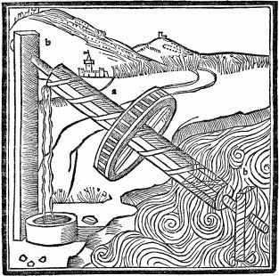
Water Wheels and Water Mills
1. Wheels on the principles that have been described above are also
constructed in rivers. Round their faces floatboards are fixed, which, on being
struck by the current of the river, make the wheel turn as they move, and thus,
by raising the water in the boxes and bringing it to the top, they accomplish
the necessary work through being turned by the mere impulse of the river,
without any treading on the part of workmen. 2. Water mills are turned on the same principle. Everything is the same in
them, except that a drum with teeth is fixed into one end of the axle. It is set
vertically on its edge, and turns in the same plane with the wheel. Next to this
larger drum there is a smaller one, also with teeth, but set horizontally, and
this is
attached (to the millstone). Thus the teeth of the drum which is fixed to the
axle make the teeth of the horizontal drum move, and cause the mill to turn. A
hopper, hanging over this contrivance, supplies the mill with corn, and meal is
produced by the same revolution. Chapter Six
The Water Screw
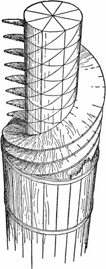
|
| Construction of the water screw(From the edition of Vitruvius by Fra Giocondo, Venice, 1511) |
1. There is also the method of the screw, which raises a great quantity of water, but does not carry it as high as does the wheel. The method of constructing it is as follows. A beam is selected, the thickness of which in digits is equivalent to its length in feet. This is made perfectly round. The ends are to be divided off on their circumference with the compass into eight parts, by quadrants and octants, and let the lines be so placed that, if the beam is laid in a horizontal position, the lines on the two ends may perfectly correspond with each other, and intervals of the size of one eighth part of the circumference of the beam may be laid off on the length of it. Then, placing the beam in a horizontal position, let perfectly straight lines be drawn from one end to the other. So the intervals will be equal in the directions both of the periphery and of the length. Where the lines are drawn along the length, the cutting circles will make intersections, and definite points at the intersections.
2. When these lines have been correctly drawn, a slender withe of willow, or a straight piece cut from the agnus castus tree, is taken, smeared with liquid pitch, and fastened at the first point of intersection.
Then it is carried across obliquely to the succeeding intersections of longitudinal lines and circles, and as it advances, passing each of the points in due order and winding round, it is fastened at each intersection; and so, withdrawing from the first to the eighth point, it reaches and is fastened to the line to which its first part was fastened. Thus, it makes as much progress in its longitudinal advance to the eighth point as in its oblique advance over eight points. In the same manner, withes for the eight divisions of the diameter, fastened obliquely at the intersections on the entire longitudinal and peripheral surface, make spiral channels which naturally look just like those of a snail shell.
|
| The water screw(From the edition of Vitruvius by Fra Giocondo, Venice, 1511) |
3. Other withes are fastened on the line of the first, and on these still others, all smeared with liquid pitch, and built up until the total diameter is equal to one eighth of the length. These are covered and surrounded with boards, fastened on to protect the spiral. Then these boards are soaked with pitch, and bound together with strips of iron, so that they may not be separated by the pressure of the water. The ends of the shaft are covered with iron. To the right and left of the screw are beams, with crosspieces fastening them together at both ends. In these crosspieces are holes sheathed with iron, and into them pivots are introduced, and thus the screw is turned by the treading of men.
4. It is to be set up at an inclination corresponding to that which is produced in drawing the Pythagorean right-angled triangle: that is, let its length be divided into five parts; let three of them denote the height of the head of the screw; thus the distance from the base of the perpendicular to the nozzle of the screw at the bottom will be equal to four of those parts. A figure showing how this ought to be, has been drawn at the end of the book, right on the back.
I have now described as clearly as I could, to make them better known, the principles on which wooden engines for raising water are constructed, and how they get their motion so that they may be of unlimited usefulness through their revolutions.
Chapter Seven
The Pump of Ctesibius
1. Next I must tell about the machine of Ctesibius, which raises water to a height. It is made of bronze, and has at the bottom a pair of cylinders set a little way apart, and there is a pipe connected with each, the two running up, like the prongs of a fork, side by side to a vessel which is between the cylinders. In this vessel are valves, accurately fitting over the upper vents of the pipes, which stop up the ventholes, and keep what has been forced by pressure into the vessel from going down again.
2. Over the vessel a cowl is adjusted, like an inverted funnel, and fastened to the vessel by means of a wedge thrust through a staple, to prevent it from being lifted off by the pressure of the water that is forced in. On top of this a pipe is jointed, called the trumpet, which stands up vertically. Valves are inserted in the cylinders, beneath the lower vents of the pipes, and over the openings which are in the bottoms of the cylinders.
3. Pistons smoothly turned, rubbed with oil, and inserted from above into the cylinders, work with their rods and levers upon the air and water in the cylinders, and, as the valves stop up the openings, force and drive the water, by repeated pressure and expansion, through the vents of the pipes into the vessel, from which the cowl receives the inflated currents, and sends them up through the pipe at the top; and so water can be supplied for a fountain from a reservoir at a lower level.
4. This, however, is not the only apparatus which Ctesibius is said to have thought out, but many more of various kinds are shown by him to produce effects, borrowed from nature, by means of water pressure and compression of the air; as, for example, blackbirds singing by means of waterworks, and "angobatae," and figures that drink and move, and other things that are found to be pleasing to the eye and the ear.
5. Of these I have selected what I considered most useful and necessary, and have thought it best to speak in the preceding book about timepieces, and in this about the methods of raising water. The rest, which are not subservient to our needs, but to pleasure and amusement, may be found in the commentaries of Ctesibius himself by any who are interested in such refinements.
Chapter Eight
The Water Organ
1. With regard to water organs, however, I shall not fail with all possible brevity and precision to touch upon their principles, and to give a sufficient description of them. A wooden base is constructed, and on it is set an altar-shaped box made of bronze. Uprights, fastened together like ladders, are set up on the base, to the right and to the left (of the altar). They hold the bronze pump-cylinders, the moveable bottoms of which, carefully turned on a lathe, have iron elbows fastened to their centres and jointed to levers, and are wrapped in fleeces of wool. In the tops of the cylinders are openings, each about three digits in diameter. Close to these openings are bronze dolphins, mounted on joints and holding chains in their mouths, from which hang cymbal-shaped valves, let down under the openings in the cylinders.
2. Inside the altar, which holds the water, is a regulator shaped like an inverted funnel, under which there are cubes, each about three digits high, keeping a free space below between the lips of the regulator and the bottom of the altar. Tightly fixed on the neck of the regulator is the windchest, which supports the principal part of the contrivance, called in Greek the κανων μουσικὁς. Running longitudinally, there are four channels in it if it is a tetrachord; six, if it is a hexachord; eight, if it is an octachord.
3. Each of the channels has a cock in it, furnished with an iron handle. These handles, when turned, open ventholes from the windchest into the channels. From the channels to the canon there are vertical openings corresponding to ventholes in a board above, which board is termed πἱναξ in Greek. Between this board and the canon are inserted sliders, pierced with holes to correspond, and rubbed with oil so that they can be easily moved and slid back into place again. They close the above-mentioned openings, and are called the plinths. Their going and coming now closes and now opens the holes.
4. These sliders have iron jacks fixed to them, and connected with the keys, and the keys, when touched, make the sliders move regularly. To the upper surface of the openings in the board, where the wind finds egress from the channels, rings are soldered, and into them the reeds of all the organ pipes are inserted. From the cylinders there are connecting pipes attached to the neck of the regulator, and directed towards the ventholes in the windchest. In the pipes are valves, turned on a lathe, and set (where the pipes are connected with the cylinders). When the windchest has received the air, these valves will stop up the openings, and prevent the wind from coming back again.
5. So, when the levers are raised, the elbows draw down the bottoms of the cylinders as far as they can go; and the dolphins, which are mounted on joints, let the cymbals fall into the cylinders, thus filling the interiors with air. Then the elbows, raising the bottoms within the cylinders by repeated and violent blows, and stopping the openings above by means of the cymbals, compress the air which is enclosed in the cylinders, and force it into the pipes, through which it runs into the regulator, and through its neck into the windchest. With a stronger motion of the levers, the air is still more compressed, streams through the apertures of the cocks, and fills the channels with wind.
6. So, when the keys, touched by the hand, drive the sliders forward and draw them back regularly, alternately stopping and opening the holes, they produce resonant sounds in a great variety of melodies conforming to the laws of music.
With my best efforts I have striven to set forth an obscure subject clearly in writing, but the theory of it is not easy, nor readily understood by all, save only those who have had some practice in things of this kind. If anybody has failed to understand it, he will certainly find, when he comes to know the thing itself, that it is carefully and exquisitely contrived in all respects.
Chapter Nine
The Hodometer
1. The drift of our treatise now turns to a useful invention of the greatest ingenuity, transmitted by our predecessors, which enables us, while sitting in a carriage on the road or sailing by sea, to know how many miles of a journey we have accomplished. This will be possible as follows. Let the wheels of the carriage be each four feet in diameter, so that if a wheel has a mark made upon it, and begins to move forward from that mark in making its revolution on the surface of the road, it will have covered the definite distance of twelve and a half feet on reaching that mark at which it began to revolve.
2. Having provided such wheels, let a drum with a single tooth projecting beyond the face of its circumference be firmly fastened to the inner side of the hub of the wheel. Then, above this, let a case be firmly fastened to the body of the carriage, containing a revolving drum set on edge and mounted on an axle; on the face of the drum there are four hundred teeth, placed at equal intervals, and engaging the tooth of the drum below. The upper drum has, moreover, one tooth fixed to its side and standing out farther than the other teeth.
3. Then, above, let there be a horizontal drum, similarly toothed and contained in another case, with its teeth engaging the tooth fixed to the side of the second drum, and let as many holes be made in this (third) drum as will correspond to the number of miles—more or less, it does not matter—that a carriage can go in a day's journey. Let a small round stone be placed in every one of these holes, and in the receptacle or case containing that drum let one hole be made, with a small pipe attached, through which, when they reach that point, the stones placed in the drum may fall one by one into a bronze vessel set underneath in the body, of the carriage.
4. Thus, as the wheel in going forward carries with it the lowest drum, and as the tooth of this at every revolution strikes against the teeth of the upper drum, and makes it move along, the result will be that the upper drum is carried round once for every four hundred revolutions of the lowest, and that the tooth fixed to its side pushes forward one tooth of the horizontal drum. Since, therefore, with four hundred revolutions of the lowest drum, the upper will revolve once, the progress made will be a distance of five thousand feet or one mile. Hence, every stone, making a ringing sound as it falls, will give warning that we have gone one mile. The number of stones gathered from beneath and counted, will show the number of miles in the day's journey.
5. On board ship, also, the same principles may be employed with a few changes. An axle is passed through the sides of the ship, with its ends projecting, and wheels are mounted on them, four feet in diameter, with projecting floatboards fastened round their faces and striking the water. The middle of the axle in the middle of the ship carries a drum with one tooth projecting beyond its circumference. Here a case is placed containing a drum with four hundred teeth at regular intervals, engaging the tooth of the drum that is mounted on the axle, and having also one other tooth fixed to its side and projecting beyond its circumference.
6. Above, in another case fastened to the former, is a horizontal drum toothed in the same way, and with its teeth engaging the tooth fixed to the side of the drum that is set on edge, so that one of the teeth of the horizontal drum is struck at each revolution of that tooth, and the horizontal drum is thus made to revolve in a circle. Let holes be made in the horizontal drum, in which holes small round stones are to be placed. In the receptacle or case containing that drum, let one hole be opened with a small pipe attached, through which a stone, as soon as the obstruction is removed, falls with a ringing sound into a bronze vessel.
7. So, when a ship is making headway, whether under oars or under a gale of wind, the floatboards on the wheels will strike against the water and be driven violently back, thus turning the wheels; and they, revolving, will move the axle, and the axle the drum, the tooth of which, as it goes round, strikes one of the teeth of the second drum at each revolution, and makes it turn a little. So, when the floatboards have caused the wheels to revolve four hundred times, this drum, having turned round once, will strike a tooth of the horizontal drum with the tooth that is fixed to its side. Hence, every time the turning of the horizontal drum brings a stone to a hole, it will let the stone out through the pipe. Thus by the sound and the number, the length of the voyage will be shown in miles.
I have described how to make things that may be provided for use and amusement in times that are peaceful and without fear.
Chapter Ten
Catapults or Scorpiones
1. I shall next explain the symmetrical principles on which scorpiones and ballistae may be constructed, inventions devised for defence against danger, and in the interest of self-preservation.
The proportions of these engines are all computed from the given length of the arrow which the engine is intended to throw, and the size of the holes in the capitals, through which the twisted sinews that hold the arms are stretched, is one ninth of that length.
2. The height and breadth of the capital itself must then conform to the size of the holes. The boards at the top and bottom of the capital, which are called "peritreti," should be in thickness equal to one hole, and in breadth to one and three quarters, except at their extremities, where they equal one hole and a half. The sideposts on the right and left should be four holes high, excluding the tenons, and five twelfths of a hole thick; the tenons, half a hole. The distance from a sidepost to the hole is one quarter of a hole, and it is also one quarter of a hole from the hole to the post in the middle. The breadth of the post in the middle is equal to one hole and one eighth, the thickness, to one hole.
3. The opening in the middle post, where the arrow is laid, is equal to one fourth of the hole. The four surrounding corners should have iron plates nailed to their sides and faces, or should be studded with bronze pins and nails. The pipe, called συριγξ in Greek, has a length of nineteen holes. The strips, which some term cheeks, nailed at the right and left of the pipe, have a length of nineteen holes and a height and thickness of one hole. Two other strips, enclosing the windlass, are nailed on to these, three holes long and half a hole in breadth. The cheek nailed on to them, named the "bench," or by some the "box," and made fast by means of dove-tailed tenons, is one hole thick and seven twelfths of a hole in height. The length of the windlass is equal to... holes, the thickness of the windlass to three quarters of a hole.
4. The latch is seven twelfths of a hole in length and one quarter in thickness. So also its socket-piece. The trigger or handle is three holes in length and three quarters of a hole in breadth and thickness. The trough in the pipe is sixteen holes in length, one quarter of a hole in thickness, and three quarters in height. The base of the standard on the ground is equal to eight holes; the breadth of the standard where it is fastened into the plinth is three quarters of a hole, its thickness two thirds of a hole; the height of the standard up to the tenon is twelve holes, its breadth three quarters of a hole, and its thickness two thirds. It has three struts, each nine holes in length, half a hole in breadth, and five twelfths in thickness. The tenon is one hole in length, and the head of the standard one hole and a half in length.
5. The antefix has the breadth of a hole and one eighth, and the thickness of one hole. The smaller support, which is behind, termed in Greek ἁντἱβασιϛ, is eight holes long, three quarters of a hole broad, and two thirds thick. Its prop is twelve holes long, and has the same breadth and thickness as the smaller support just mentioned. Above the smaller support is its socket-piece, or what is called the cushion, two and a half holes long, one and a half high, and three quarters of a hole broad. The windlass cup is two and seven twelfths holes long, two thirds of a hole thick, and three quarters broad. The crosspieces with their tenons have the length of... holes, the breadth of three quarters, and the thickness of two thirds of a hole. The length of an arm is seven holes, its thickness at its base two thirds of a hole, and at its end one half a hole; its curvature is equal to two thirds of a hole.
6. These engines are constructed according to these proportions or with additions or diminutions. For, if the height of the capitals is greater than their width—when they are called "high-tensioned,"—something should be taken from the arms, so that the more the tension is weakened by height of the capitals, the more the strength of the blow is increased by shortness of the arms. But if the capital is less high,—when the term "low-tensioned" is used,—the arms, on account of their strength, should be made a little longer, so that they may be drawn easily. Just as it takes four men to raise a load with a lever five feet long, and only two men to lift the same load with a ten-foot lever, so the longer the arms, the easier they are to draw, and the shorter, the harder.
I have now spoken of the principles applicable to the parts and proportions of catapults.
Chapter Eleven
Ballistae
1. Ballistae are constructed on varying principles to produce an identical result. Some are worked by handspikes and windlasses, some by blocks and pulleys, others by capstans, others again by means of drums. No ballista, however, is made without regard to the given amount of weight of the stone which the engine is intended to throw. Hence their principle is not easy for everybody, but only for those who have knowledge of the geometrical principles employed in calculation and in multiplication.
2. For the holes made in the capitals through the openings of which are stretched the strings made of twisted hair, generally women's, or of sinew, are proportionate to the amount of weight in the stone which the ballista is intended to throw, and to the principle of mass, as in catapults the principle is that of the length of the arrow. Therefore, in order that those who do not understand geometry may be prepared beforehand, so as not to be delayed by having to think the matter out at a moment of peril in war, I will set forth what I myself know by experience can be depended upon, and what I have in part gathered from the rules of my teachers, and wherever Greek weights bear a relation to the measures, I shall reduce and explain them so that they will express the same corresponding relation in our weights.
3. A ballista intended to throw a two-pound stone will have a hole of five digits in its capital; four pounds, six digits; and six pounds, seven digits; ten pounds, eight digits; twenty pounds, ten digits; forty pounds, twelve and a half digits; sixty pounds, thirteen and a half digits; eighty pounds, fifteen and three quarters digits; one hundred pounds, one foot and one and a half digits; one hundred and twenty pounds, one foot and two digits; one hundred and forty pounds, one foot and three digits; one hundred and sixty pounds, one foot and a quarter; one hundred and eighty pounds, one foot and five digits; two hundred pounds, one foot and six digits; two hundred and forty pounds, one foot and seven digits; two hundred and eighty pounds, one foot and a half; three hundred and twenty pounds, one foot and nine digits; three hundred and sixty pounds, one foot and ten digits.
4. Having determined the size of the hole, design the "scutula," termed in Greek περἱτρητοϛ,... holes in length and two and one sixth in breadth. Bisect it by a line drawn diagonally from the angles, and after this bisecting bring together the outlines of the figure so that it may present a rhomboidal design, reducing it by one sixth of its length and one fourth of its breadth at the (obtuse) angles. In the part composed by the curvatures into which the points of the angles run out, let the holes be situated, and let the breadth be reduced by one sixth; moreover, let the hole be longer than it is broad by the thickness of the bolt. After designing the scutula, let its outline be worked down to give it a gentle curvature.
5. It should be given the thickness of seven twelfths of a hole. The boxes are two holes (in height), one and three quarters in breadth, two thirds of a hole in thickness except the part that is inserted in the hole, and at the top one third of a hole in breadth. The sideposts are five holes and two thirds in length, their curvature half a hole, and their thickness thirty-seven forty-eighths of a hole. In the middle their breadth is increased as much as it was near the hole in the design, by the breadth and thickness of... hole; the height by one fourth of a hole.
6. The (inner) strip on the "table" has a length of eight holes, a breadth and thickness of half a hole. Its tenons are one hole and one sixth long, and one quarter of a hole in thickness. The curvature of this strip is three quarters of a hole. The outer strip has the same breadth and thickness (as the inner), but the length is given by the obtuse angle of the design and the breadth of the sidepost at its curvature. The upper strips are to be equal to the lower; the crosspieces of the "table," one half of a hole.
7. The shafts of the "ladder" are thirteen holes in length, one hole in thickness; the space between them is one hole and a quarter in breadth, and one and one eighth in depth. Let the entire length of the ladder on its upper surface—which is the one adjoining the arms and fastened to the table—be divided into five parts. Of these let two parts be given to the member which the Greeks call the χελὡνιον, its breadth being one and one sixth, its thickness one quarter, and its length eleven holes and one half; the claw projects half a hole and the "winging" three sixteenths of a hole. What is at the axis which is termed the... face... the crosspieces of three holes?
8. The breadth of the inner slips is one quarter of a hole; their thickness one sixth. The cover-joint or lid of the chelonium is dove-tailed into the shafts of the ladder, and is three sixteenths of a hole in breadth and one twelfth in thickness. The thickness of the square piece on the ladder is three sixteenths of a hole,... the diameter of the round axle will be equal to that of the claw, but at the pivots seven sixteenths of a hole.
9. The stays are... holes in length, one quarter of a hole in breadth at the bottom, and one sixth in thickness at the top. The base, termed ἑσχἁρα, has the length of... holes, and the anti-base of four holes; each is one hole in thickness and breadth. A supporter is jointed on, halfway up, one and one half holes in breadth and thickness. Its height bears no relation to the hole, but will be such as to be serviceable. The length of an arm is six holes, its thickness at the base two thirds of a hole, and at the end one half a hole.
I have now given those symmetrical proportions of ballistae and catapults which I thought most useful. But I shall not omit, so far as I can express it in writing, the method of stretching and tuning their strings of twisted sinew or hair.
Chapter Twelve
The Stringing and Tuning of Catapults
1. Beams of very generous length are selected, and upon them are nailed socket-pieces in which windlasses are inserted. Midway along their length the beams are incised and cut away to form framings, and in these cuttings the capitals of the catapults are inserted, and prevented by wedges from moving when the stretching is going on. Then the bronze boxes are inserted into the capitals, and the little iron bolts, which the Greeks call ἑπιξυγἱδες, are put in their places in the boxes.
2. Next, the loops of the strings are put through the holes in the capitals, and passed through to the other side; next, they are put upon the windlasses, and wound round them in order that the strings, stretched out taut on them by means of the handspikes, on being struck by the hand, may respond with the same sound on both sides. Then they are wedged tightly into the holes so that they cannot slacken. So, in the same manner, they are passed through to the other side, and stretched taut on the windlasses by means of the handspikes until they give the same sound. Thus with tight wedging, catapults are tuned to the proper pitch by musical sense of hearing.
On these things I have said what I could. There is left for me, in the matter of sieges, to explain how generals can win victories and cities be defended, by means of machinery.
Chapter Thirteen
Siege Machines
1. It is related that the battering ram for sieges was originally invented as follows. The Carthaginians pitched their camp for the siege of Cadiz. They captured an outwork and attempted to destroy it. But having no iron implements for its destruction, they took a beam, and, raising it with their hands, and driving the end of it repeatedly against the top of the wall, they threw down the top courses of stones, and thus, step by step in regular order, they demolished the entire redoubt.
2. Afterwards a carpenter from Tyre, Bright by name and by nature, was led by this invention into setting up a mast from which he hung another crosswise like a steelyard, and so, by swinging it vigorously to and fro, he threw down the wall of Cadiz. Geras of Chalcedon was the first to make a wooden platform with wheels under it, upon which he constructed a framework of uprights and crosspieces, and within it he hung the ram, and covered it with oxhide for the better protection of the men who were stationed in the machine to batter the wall. As the machine made but slow progress, he first gave it the name of the tortoise of the ram.
3. These were the first steps then taken towards that kind of machinery, but afterwards, when Philip, the son of Amyntas, was besieging Byzantium, it was developed in many varieties and made handier by Polyidus the Thessalian. His pupils were Diades and Charias, who served with Alexander. Diades shows in his writings that he invented moveable towers, which he used also to take apart and carry round with the army, and likewise the borer, and the scaling machine, by means of which one can cross over to the wall on a level with the top of it, as well as the destroyer called the raven, or by others the crane.
4. He also employed the ram mounted on wheels, an account of which he left in his writings. As for the tower, he says that the smallest should be not less than sixty cubits in height and seventeen in breadth, but diminishing to one fifth less at the top; the uprights for the tower being nine inches at the bottom and half a foot at the top. Such a tower, he says, ought to be ten stories high, with windows in it on all sides.
5. His larger tower, he adds, was one hundred and twenty cubits high and twenty-three and one half cubits broad, diminishing like the other to one fifth less; the uprights, one foot at the bottom and six digits at the top. He made this large tower twenty stories high, each story having a gallery round it, three cubits wide. He covered the towers with rawhide to protect them from any kind of missile.
6. The tortoise of the battering ram was constructed in the same way. It had, however, a base of thirty cubits square, and a height, excluding the pediment, of thirteen cubits; the height of the pediment from its bed to its top was seven cubits. Issuing up and above the middle of the roof for not less than two cubits was a gable, and on this was reared a small tower four stories high, in which, on the top floor, scorpiones and catapults were set up, and on the lower floors a great quantity of water was stored, to put out any fire that might be thrown on the tortoise. Inside of this was set the machinery of the ram, termed in Greek κριοδὁχη, in which was placed a roller, turned on a lathe, and the ram, being set on top of this, produced its great effects when swung to and fro by means of ropes. It was protected, like the tower, with rawhide.
7. He explained the principles of the borer as follows: that the machine itself resembled the tortoise, but that in the middle it had a pipe lying between upright walls, like the pipe usually found in catapults and ballistae, fifty cubits in length and one cubit in height, in which a windlass was set transversely. On the right and left, at the end of the pipe, were two blocks, by means of which the iron-pointed beam, which lay in the pipe, was moved. There were numerous rollers enclosed in the pipe itself under the beam, which made its movements quicker and stronger. Numerous arches were erected along the pipe above the beam which was in it, to hold up the rawhide in which this machine was enveloped.
8. He thought it needless to write about the raven, because he saw that the machine was of no value. With regard to the scaling machine, termed in Greek ἑπιβἁθρα, and the naval contrivances which, as he wrote, could be used in boarding ships, I have observed that he merely promised with some earnestness to explain their principles, but that he has not done so.
I have set forth what was written by Diades on machines and their construction. I shall now set forth the methods which I have learned from my teachers, and which I myself believe to be useful.
Chapter Fourteen
The Tortoise
1. A tortoise intended for the filling of ditches, and thereby to make it possible to reach the wall, is to be made as follows. Let a base, termed in Greek ἑσχἁρα, be constructed, with each of its sides twenty-one feet long, and with four crosspieces. Let these be held together by two others, two thirds of a foot thick and half a foot broad; let the crosspieces be about three feet and a half apart, and beneath and in the spaces between them set the trees, termed in Greek ἁμαξὁποδες, in which the axles of the wheels turn in iron hoops. Let the trees be provided with pivots, and also with holes through which levers are passed to make them turn, so that the tortoise can move forward or back or towards its right or left side, or if necessary obliquely, all by the turning of the trees.
2. Let two beams be laid on the base, projecting for six feet on each side, round the projections of which let two other beams be nailed, projecting seven feet beyond the former, and of the thickness and breadth prescribed in the case of the base. On this framework set up posts mortised into it, nine feet high exclusive of their tenons, one foot and a quarter square, and one foot and a half apart. Let the posts be tied together at the top by mortised beams. Over the beams let the rafters be set, tied one into another by means of tenons, and carried up twelve feet high. Over the rafters set the square beam by which the rafters are bound together.
3. Let the rafters themselves be held together by bridgings, and covered with boards, preferably of holm oak, or, this failing, of any other material which has the greatest strength, except pine or alder. For these woods are weak and easily catch fire. Over the boardings let there be placed wattles very closely woven of thin twigs as fresh as possible. Let the entire machine be covered with rawhide sewed together double and stuffed with seaweed or straw soaked in vinegar. In this way the blows of ballistae and the force of fires will be repelled by them.
Chapter Fifteen
Hegetor's Tortoise
1. There is also another kind of tortoise, which has all the other details as described above except the rafters, but it has round it a parapet and battlements of boards, and eaves sloping downwards, and is covered with boards and hides firmly fastened in place. Above this let clay kneaded with hair be spread to such a thickness that fire cannot injure the machine. These machines can, if need be, have eight wheels, should it be necessary to modify them with reference to the nature of the ground. Tortoises, however, which are intended for excavating, termed in Greek ὁρυκτἱδες, have all the other details as described above, but their fronts are constructed like the angles of triangles, in order that when missiles are shot against them from a wall, they may receive the blows not squarely in front, but glancing from the sides, and those excavating within may be protected without danger.
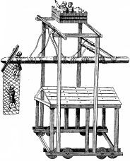
|
| From a MS. of the sixteenth century (Wescher's Poliorcétique des Grecs) |
2. It does not seem to me out of place to set forth the principles on which Hegetor of Byzantium constructed a tortoise. The length of its base was sixty-three feet, the breadth forty-two. The corner posts, four in number, which were set upon this framework, were made of two timbers each, and were thirty-six feet high, a foot and a quarter thick, and a foot and a half broad. The base had eight wheels by means of which it was moved about. The height of these wheels was six and three quarters feet, their thickness three feet. Thus constructed of three pieces of wood, united by alternate opposite dovetails and bound together by cold-drawn iron plates, they revolved in the trees or amaxopodes.
3. Likewise, on the plane of the crossbeams above the base, were erected posts eighteen feet high, three quarters of a foot broad, two thirds of a foot thick, and a foot and three quarters apart; above these, framed beams, a foot broad and three quarters of a foot thick, held the whole structure together; above this the rafters were raised, with an elevation of twelve feet; a beam set above the rafters united their joinings. They also had bridgings fastened transversely, and a flooring laid on them protected the parts beneath.
4. It had, moreover, a middle flooring on girts, where scorpiones and catapults were placed. There were set up, also, two framed uprights forty-five feet long, a foot and a half in thickness, and three quarters of a foot in breadth, joined at the tops by a mortised crossbeam and by another, halfway up, mortised into the two shafts and tied in place by iron plates. Above this was set, between the shafts and the crossbeams, a block pierced on either side by sockets, and firmly fastened in place with clamps. In this block were two axles, turned on a lathe, and ropes fastened from them held the ram.
5. Over the head of these (ropes) which held the ram, was placed a parapet fitted out like a small tower, so that, without danger, two soldiers, standing in safety, could look out and report what the enemy were attempting. The entire ram had a length of one hundred and eighty feet, a breadth at the base of a foot and a quarter, and a thickness of a foot, tapering at the head to a breadth of a foot and a thickness of three quarters of a foot.
6. This ram, moreover, had a beak of hard iron such as ships of war usually have, and from the beak iron plates, four in number, about fifteen feet long, were fastened to the wood. From the head to the very heel of the beam were stretched cables, three in number and eight digits thick, fastened just as in a ship from stem to stern continuously, and these cables were bound with cross girdles a foot and a quarter apart. Over these the whole ram was wrapped with rawhide. The ends of the ropes from which the ram hung were made of fourfold chains of iron, and these chains were themselves wrapped in rawhide.
7. Likewise, the projecting end of the ram had a box framed and constructed of boards, in which was stretched a net made of rather large ropes, over the rough surfaces of which one easily reached the wall without the feet slipping. And this machine moved in six directions, forward (and backward), also to the right or left, and likewise it was elevated by extending it upwards and depressed by inclining it downwards. The machine could be elevated to a height sufficient to throw down a wall of about one hundred feet, and likewise in its thrust it covered a space from right to left of not less than one hundred feet. One hundred men controlled it, though it had a weight of four thousand talents, which is four hundred and eighty thousand pounds.
Chapter Sixteen
Measures of Defence
1. With regard to scorpiones, catapults, and ballistae, likewise with regard to tortoises and towers, I have set forth, as seemed to me especially appropriate, both by whom they were invented and in what manner they should be constructed. But I have not considered it as necessary to describe ladders, cranes, and other things, the principles of which are simpler, for the soldiers usually construct these by themselves, nor can these very machines be useful in all places nor in the same way, since fortifications differ from each other, and so also the bravery of nations. For siege works against bold and venturesome men should be constructed on one plan, on another against cautious men, and on still another against the cowardly.
2. And so, if any one pays attention to these directions, and by selection adapts their various principles to a single structure, he will not be in need of further aids, but will be able, without hesitation, to design such machines as the circumstances or the situations demand. With regard to works of defence, it is not necessary to write, since the enemy do not construct their defences in conformity with our books, but their contrivances are frequently foiled, on the spur of the moment, by some shrewd, hastily conceived plan, without the aid of machines, as is said to have been the experience of the Rhodians.
3. For Diognetus was a Rhodian architect, to whom, as an honour, was granted out of the public treasury a fixed annual payment commensurate with the dignity of his art. At this time an architect from Aradus, Callias by name, coming to Rhodes, gave a public lecture, and showed a model of a wall, over which he set a machine on a revolving crane with which he seized an helepolis as it approached the fortifications, and brought it inside the wall. The Rhodians, when they had seen this model, filled with admiration, took from Diognetus the yearly grant and transferred this honour to Callias.
4. Meanwhile, king Demetrius, who because of his stubborn courage was called Poliorcetes, making war on Rhodes, brought with him a famous Athenian architect named Epimachus. He constructed at enormous expense, with the utmost care and exertion, an helepolis one hundred and thirty-five feet high and sixty feet broad. He strengthened it with hair and rawhide so that it could withstand the blow of a stone weighing three hundred and sixty pounds shot from a ballista; the machine itself weighed three hundred and sixty thousand pounds. When Callias was asked by the Rhodians to construct a machine to resist this helepolis, and to bring it within the wall as he had promised, he said that it was impossible.
5. For not all things are practicable on identical principles, but there are some things which, when enlarged in imitation of small models, are effective, others cannot have models, but are constructed independently of them, while there are some which appear feasible in models, but when they have begun to increase in size are impracticable, as we can observe in the following instance. A half inch, inch, or inch and a half hole is bored with an auger, but if we should wish, in the same manner, to bore a hole a quarter of a foot in breadth, it is impracticable, while one of half a foot or more seems not even conceivable.
6. So too, in some models it is seen how they appear practicable on the smallest scale and likewise on a larger. And so the Rhodians, in the same manner, deceived by the same reasoning, inflicted injury and insult on Diognetus. Therefore, when they saw the enemy stubbornly hostile, slavery threatening them because of the machine which had been built to take the city, and that they must look forward to the destruction of their state, they fell at the feet of Diognetus, begging him to come to the aid of the fatherland. He at first refused.
7. But after free-born maidens and young men came with the priests to implore him, he promised to do it on condition that if he took the machine it should be his property. When these terms had been agreed upon, he pierced the wall in the place where the machine was going to approach it, and ordered all to bring forth from both public and private sources all the water, excrement, and filth, and to pour it in front of the wall through pipes projecting through this opening. After a great amount of water, filth, and excrement had been poured out during the night, on the next day the helepolis moving up, before it could reach the wall, came to a stop in the swamp made by the moisture, and could not be moved forwards, nor later even backwards. And so Demetrius, when he saw that he had been baffled by the wisdom of Diognetus, withdrew with his fleet.
8. Then the Rhodians, freed from the war by the cunning of Diognetus, thanked him publicly, and decorated him with all honours and distinctions. Diognetus brought that helepolis into the city, set it up in a public place, and put on it an inscription: "Diognetus out of the spoils of the enemy dedicated this gift to the people." Therefore, in works of defence, not merely machines, but, most of all, wise plans must be prepared.
9. Likewise at Chios, when the enemy had prepared storming bridges on their ships, the Chians, by night, carried out earth, sand, and stones into the sea before their walls. So, when the enemy, on the next day, tried to approach the walls, their ships grounded on the mound beneath the water, and could not approach the wall nor withdraw, but pierced with fire-darts were burned there. Again, when Apollonia was being besieged, and the enemy were thinking, by digging mines, to make their way within the walls without exciting suspicion, and this was reported by scouts to the people of Apollonia, they were much disturbed and alarmed by the news, and having no plans for defence, they lost courage, because they could not learn either the time or the definite place where the enemy would come out.
10. But at this time Trypho, the Alexandrine architect, was there. He planned a number of countermines inside the wall, and extending them outside the wall beyond the range of arrows, hung up in all of them brazen vessels. The brazen vessels hanging in one of these mines, which was in front of a mine of the enemy, began to ring from the strokes of their iron tools. So from this it was ascertained where the enemy, pushing their mines, thought to enter. The line being thus found out, he prepared kettles of hot water, pitch, human excrement, and sand heated to a glow. Then, at night, he pierced a number of holes, and pouring the mixture suddenly through them, killed all the enemy who were engaged in this work.
11. In the same manner, when Marseilles was being besieged, and they were pushing forward more than thirty mines, the people of Marseilles, distrusting the entire moat in front of their wall, lowered it by digging it deeper. Thus all the mines found their outlet in the moat. In places where the moat could not be dug they constructed, within the walls, a basin of enormous length and breadth, like a fish pond, in front of the place where the mines were being pushed, and filled it from wells and from the port. And so, when the passages of the mine were suddenly opened, the immense mass of water let in undermined the supports, and all who were within were overpowered by the mass of water and the caving in of the mine.
12. Again, when a rampart was being prepared against the wall in front of them, and the place was heaped up with felled trees and works placed there, by shooting at it with the ballistae red-hot iron bolts they set the whole work on fire. And when a ram-tortoise had approached to batter down the wall, they let down a noose, and when they had caught the ram with it, winding it over a drum by turning a capstan, having raised the head of the ram, they did not allow the wall to be touched, and finally they destroyed the entire machine by glowing fire-darts and the blows of ballistae. Thus by such victory, not by machines but in opposition to the principle of machines, has the freedom of states been preserved by the cunning of architects.
Such principles of machines as I could make clear, and as I thought most serviceable for times of peace and of war, I have explained in this book. In the nine earlier books I have dealt with single topics and details, so that the entire work contains all the branches of architecture, set forth in ten books.
Here ends Vitruvius' Ten Books on Architecture.